
Ethernet 2 Door Controller (Up to 8 doors)
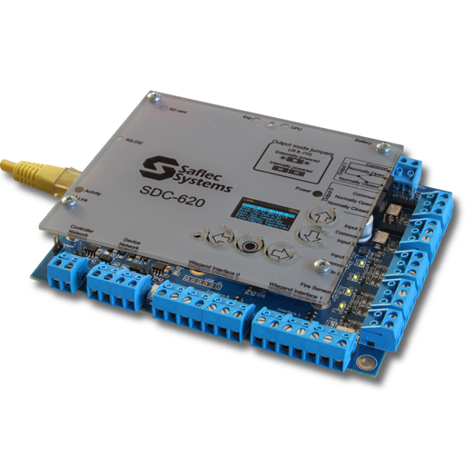
Product Code: SDC-620
This controller is the replacement for the legacy SDC-520 controller and incorporates a host of new design features and increased functionality. Most notably amongst these are the Micro SD inclusion for increased capacities, the OLED control module for easy setup & local diagnostics, and OSDP secure channel compatibility.
Key Features
Note:
This unit is designed to suit smaller installations and does not support features like multi-dropped controllers, expansion boards or events across controllers.
If you require any further information, please contact our sales department…
- Multiple Door control unit (2 doors onboard)
- Expansion Header Module (for I/O Expansion)
- 1 000 000 cards
- 6.5 Million offline transactions
- On-board TCP/IP communications
- Complete intelligent offline operation
- Mains monitoring with a battery charging circuit
- Low voltage cutoff to prevent battery draining
- 2 onboard Wiegand interface connections
- 4 programmable digital inputs
- 2 relay outputs (powered or potential-free)
- Can connect up to 15 Controllers on RS-485
- 5A 15V DC power supply
- Battery backup (7Ah battery included)
- RS-485 communications for additional readers
- Network-capable remote firmware upgrades
- Secure enclosure designed for easy installation
- 3.25 Miliion offline system logs
- Pushbutton or egress override support
- 256 powerful offline event/action combinations
- Diagnostic LEDs for easy testing
- Independent dedicated tamper and fire inputs
- Robust isolated RS-485 controller network
- RS-485 reader network (16 terminals)
About the product
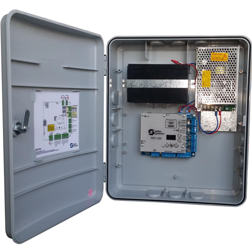
This is an intelligent Ethernet (TCP/IP) system controller with two relay outputs (potential free contact/powered output) and four programmable digital inputs capable of controlling two full normal doors/one bi-directional turnstile or one booth/mantrap. With the addition of Remote IO boards, this unit can be expanded to 8 doors per controller. It has 2 Wiegand interface connections on board and can handle up to 16 terminals on its robust isolated multi-drop RS-485 terminal network. Remote I/O units can be connected either to control more doors (to a maximum of 8 doors per controller) or simply for extra I/O points for controlling other devices. It can be connected to other controllers using a robust multi-drop RS-485 controller network which has isolation that protects the controllers on the network from electrical spikes of up to 2.4kV. The unit comes with a 15Vdc 5A power supply with a battery backup of 7Ah and is mounted in a secure enclosure with a lockable door.
The SDC-620 can be networked to other SDC-320, SDC-620, or SDC-650 controllers to create a fully controllable networked access control system. This gives the advantage of central, flexible control over configuration, and user access rights and provides centralized event reporting. Each controller is part of a network but can run independently making its own decisions and storing all events if communication to the SACS Server is interrupted or lost. All events are automatically uploaded to the central SACS Server when communication is re-established.
The SDC-620 is supplied as a complete unit in a lockable cabinet with a power supply and battery. However, the controller can also be supplied as a PCB only.
Installation
There is a label on the inside of the cabinet door that clearly shows the connections for readers, inputs & outputs. The unit has dual-mode relays that can be set as powered outputs or potential-free relays (using the indicated jumpers) that allow you to switch any lock or electrical device.
The Controller/s communicates with the SACS Server via the standard TCP/IP protocol of a LAN/WAN using the onboard RJ45 connector. The controllers can also connect to 15 additional controllers via its’ RS-485 controller network. The unit can be configured to use a DHCP-assigned IP Address or be given a fixed/static IP address (recommended). The initial IP Address settings are done via the onboard OLED Display on the controller and, once communication is established, the access control configuration of the doors, reader, etc. is done using the SACS Software.
There are diagnostic LEDs mounted close to their relevant terminals to assist with trouble-free installation. End-of-line resistors can be switched into the circuit as required using the indicated jumpers. External terminating resistors are not required.
Operation
Any changes made at the PC are immediately communicated and stored at the controller. When a user presents their card to the reader, the controller identifies them and permits or denies access as appropriate.